Get to Know Everything about the UML Activity Diagram [with Methods]
Are you a business aspirant wanting to know about UML activity diagrams to better understand the system’s flow? Worry no more. If that is your concern, this guidepost will significantly help. In this discussion, you will learn the complete definition of a UML activity diagram. It includes its benefits and how to create one. So, if you desire to learn more about the topic, read this article immediately.
- Part 1. Introduction to UML Activity Diagram
- Part 2. Benefits of A UML Activity Diagram
- Part 3. Easiest Way to Create A UML Activity Diagram
- Part 4. FAQs about UML Activity Diagram
Part 1. Introduction to UML Activity Diagram
Another crucial UML diagram for describing the system's dynamic elements is the Activity diagram. An activity diagram is a flowchart showing how one activity leads to another. The action might be referred to as a system operation. One operation leads to the next in the control flow. This flow may be parallel, contemporary, or branched. Activity diagrams use many features, such as fork, join, etc., to cope with all types of flow control. Similar to other diagrams, activity diagrams serve similar fundamental goals. It captures the system's dynamic behavior.

An activity is a specific system function. Activity diagrams build the executable system utilizing forward and reverse engineering approaches. It is also to visualize the dynamic nature of a system. The message portion is the only item the activity diagram is missing. No message flow from one activity to another is shown. Occasionally, an activity diagram is used in place of a flowchart. The diagrams are not flowcharts, despite their appearance. It displays various flows, including single, parallel, branching, and concurrent.
UML Activity Diagram Symbols
After knowing the definition of a UML activity diagram, it is crucial to understand the various symbols of the diagram. These are the most common symbols and shapes on the activity diagram.
Start Symbol
It represents in an activity diagram the start of a process or workflow. It can be used independently or with a note symbol that describes the starting position.

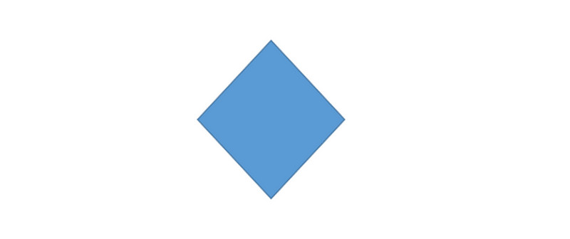
Decision Symbol
A decision is shown, and at least two paths branch off with condition language so users can see their possibilities. The symbol serves as a frame or container to illustrate the branching or joining of numerous flows.
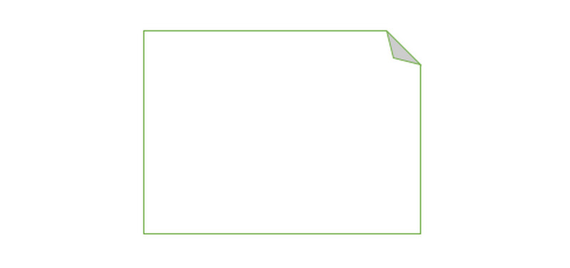
Note Symbol
Allows those involved in the diagram's creation or collaboration to convey additional messages that don't belong in the diagram. Add remarks to increase clarity and specificity.
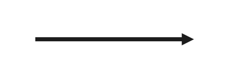
Connector Symbol
It displays the activity's directional flow or control flow. An incoming arrow initiates an activity's step; after the step is finished, the flow shifts to an outgoing arrow.
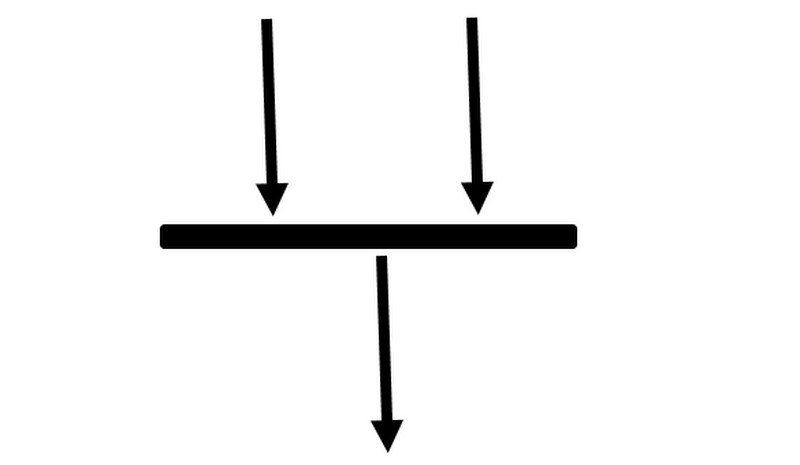
Joint Symbol/Synchronization Bar
It combines two ongoing processes and reintroduces them to a flow in which only one process is active at once. A thick vertical or horizontal line is used to represent it.
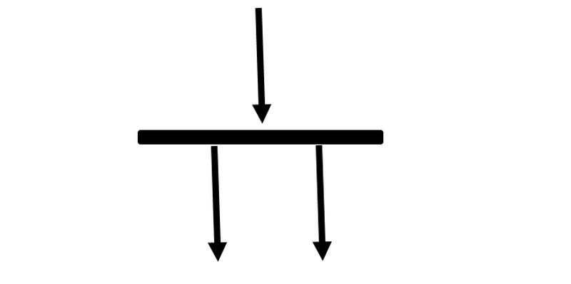
Fork Symbol
It divides a single activity flow into two parallel processes. It is portrayed as a junction of several arrowed lines.
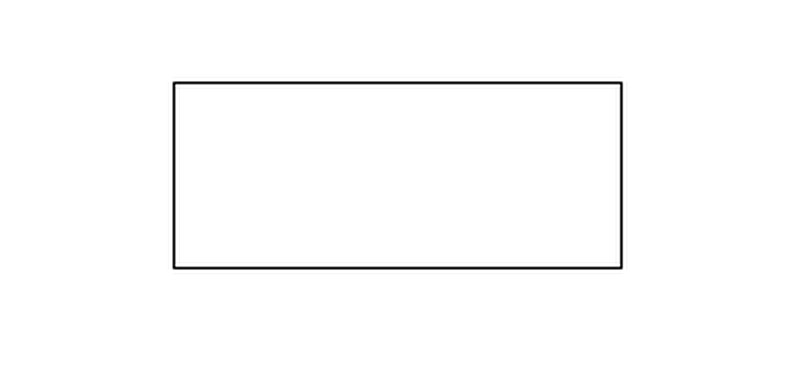
Activity Symbol
Shows the actions that comprise a modeled process. The primary components of an activity diagram are these symbols, each with a brief description incorporated into its design.
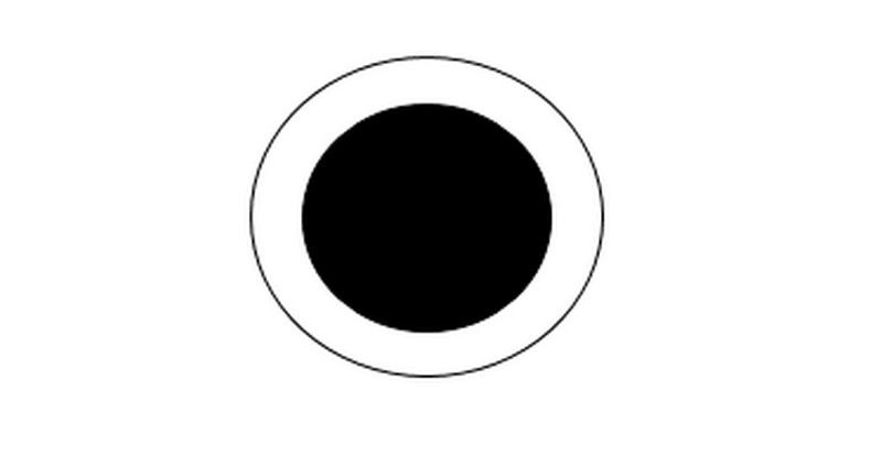
End Symbol
It reflects the conclusion of all activity flows and the end of an activity.
Part 2. Benefits of A UML Activity Diagram
◆ This diagram can represent conditional or simultaneous processes. Activity diagrams in information technology describe the real workflow behavior of a system. This diagram describes the actual status of a system's activities by depicting the entire sequence of actions taken.
◆ Analysts and stakeholders can typically understand the activity diagram with ease.
◆ It is easy to comprehend by both BAs and end users. The activity diagram in UML for the IT Business Analyst is the one the IT BA finds most helpful for illustrating workflow.
◆ They are commonly viewed as a crucial tool in an analyst's toolbox because they are among the most user-friendly diagrams accessible.
Part 3. Easiest Way to Create A UML Activity Diagram
Using MindOnMap would be helpful when trying to make a UML activity diagram. It has an easy-to-understand layout with basic methods, perfect for non-professional users. In addition, This UML activity diagram creator can offer everything you need to create an activity diagram. The tool lets you use lines, arrows, shapes, text, and more. It also allows you to put different colors on the shapes. Also, MindOnMap offers free-to-use themes. This way, you can make your diagram attractive and unique. Moreover, the tool allows you to share your work with other users by sharing the link. Then, after sharing, you can let them edit your diagram. It is helpful when you are brainstorming with your teams, partner, or with your organization. Furthermore, you can save your UML activity diagram in various formats. It includes JPG, PNG, SVG, DOC, PDF, and more.
Secure Download
Secure Download
Visit the MindOnMap website on your browser. The online UML activity diagram maker is accessible on Google, Firefox, Edge, Explorer, etc. After that, you have to sign up to get your MindOnMap account. Then, click the Create Your Mind Map button.

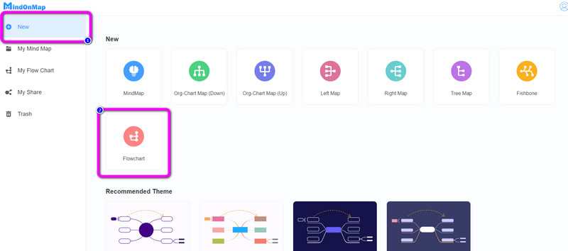
Navigate to the New option on the left interface. Then, select the Flowchart option.
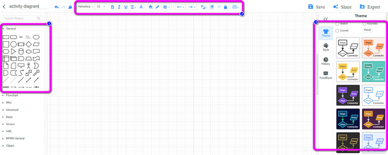
Once you are on the main interface, there are numerous elements you can see. Click the General menu on the left interface to see various shapes and connecting lines. On the right interface, you can use free Themes for the diagram. Also, on the upper interface, you can use them to color the shapes, resize the font size, change font style, and more.
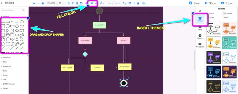
Drag and drop the shapes you need to use on the diagram. Then, to add text inside the shapes, double-left-click the shapes. Also, to add colors to each shape, click the shape and navigate to the Fill Color option, and choose your desired color.
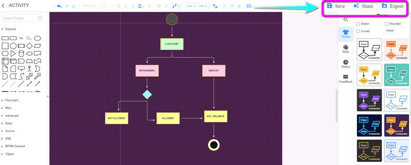
After creating a UML activity diagram, save it by clicking the Save button on the upper right part of the interface. To share your diagram with other users, click the Share button and copy the link. Then, click the Export option to export the diagram into various output formats like PNG, JPG, PDF, SVG, DOC, and more.
Further Reading
Part 4. FAQs about UML Activity Diagram
What is the difference between a UML activity diagram and a flowchart?
The activity diagram is a UML behavior diagram. It illustrates the workflow of the system's step-by-step actions. In contrast, a flowchart is a graphical diagram that shows the order of steps to solve a problem. This is the primary distinction between an activity diagram and a flowchart.
What is the difference between a UML activity diagram and a sequence diagram?
The workflow of a system is modeled using UML, represented by the activity diagram. The Sequence diagram, on the other hand, represents the UML used to show the series of calls made by a system to carry out a particular capability.
Where to use Activity Diagrams?
The system's activity flow can be modeled using an activity diagram. Several systems can be present in one application. These systems are also depicted in activity diagrams, showing how information moves between them. The activities, which are business requirements, are modeled using this diagram—the graphic affects business comprehension more than implementation specifics.
Conclusion
With all the information above, you have learned everything you need regarding the UML activity diagram. Also, the post introduced you to one of the ultimate UML activity diagram creators you can use, which is MindOnMap.