What is SDL Diagram and How to Create Using the Best Diagram Makers
SDL is a graphical modeling language and is also considered a broad-spectrum language useful for detailed and high-level modeling. It is extensively used across various fields ranging from telecommunications, aircraft, medical, packaging, railway control, and automotive systems. This allows you to interpret and analyze a system or a model in SDL clearly.
One of the main benefits of this graphical language is to eliminate ambiguity. With it, you can benefit from clarity, scalability, consistency, mathematical rigor, etc. On the other hand, this article will explain how to draw an SDL diagram. You may also test out some of the examples provided here.

- Part 1. What is SDL Diagram
- Part 2. Symbols for Drawing SDL Diagram
- Part 3. SDL Diagram Examples
- Part 4. How to Create an SDL Diagram
- Part 5. FAQs on SDL Diagram
Part 1. What is SDL Diagram
The Specification and Description Language, or SDL Diagram for short, is graphical modeling that aims to interpret and analyze a system without ambiguity. As mentioned earlier, this diagram is typical for modeling systems and machines in industries, including telecommunication, aviation, automatic, and medical fields. The primary purpose of this modeling language is to describe the behaviors and system's components reactively, concurrently, and in real-time.
The diagram is made up of three building blocks. There is a system definition, block, and process. The system definition specifies the system's major blocks like servers and clients. Meanwhile, the block is there to show more details. From the name itself, the process shows the processing steps on every block.
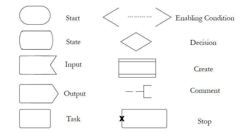
Part 2. Symbols for Drawing SDL Diagram
Before you can make an SDL diagram, you should have the essential knowledge and comprehension of the SDL shapes and symbols, especially how they work or function. In actual fact, there are tons of approaches to design a system in SDL. In that case, we have listed the shapes and symbols commonly used in creating a diagram for SDL. Therefore, here are the SDL diagram shapes you should know when drawing an SDL diagram.
Part 3. SDL Diagram Examples
Suppose you are looking for inspiration and you need examples to refer to. In that case, you may look into the examples given below.
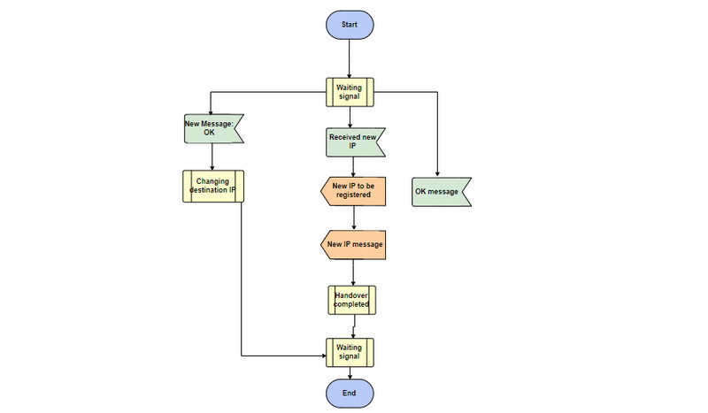
Procedure SDL Template
As we know, SDL can show how the components in a system work in real-time. In this particular example, the process of registering an IP is shown. The system starts and waits for a signal to receive a new IP. After that, the process of receiving takes place, followed by the handover process. When it ends, the system will wait for a signal, and from there, the procedure will stop.
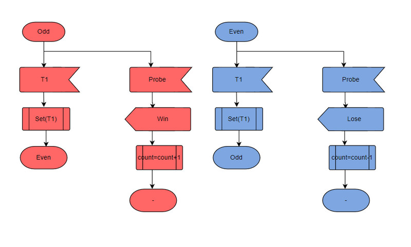
Game SDL Template
The example below depicts the process of creating a game process. This template is beneficial for online gaming software. There are components and the behavior of a process from one to another. You may also modify this gaming SDL diagram template.
Part 4. How to Create an SDL Diagram
The learnings about the SDL diagram would not be helpful if you do not apply them to the actual scenario. Thus, to make the drawing of SDL possible, it is essential to get the right drawing tool. Here we have two of the most recommended tools for creating SDL diagrams. Learn further by reading the descriptions and step-by-step procedure of both programs below.
1. MindOnMap
If you are looking for an easy flowchart, diagram, or chart creator, you should look no further than MindOnMap. It enables users to simply generate diagrams online. So, there is no need for you to download a separate program on your device. With a browser and a cyber connection, you are good to go. It provides the basic shapes and figures to help you generate the needed flowcharts and diagrams. Furthermore, it can assist you with the layout or design of your SDL diagram using the layouts offered by the tool.
Secure Download
Secure Download
Apart from SDL, the tool facilitates treemap, fishbone, and organization chart creation. The best part is enhancing your diagram's shape color, connectors, branches, etc. Also, you can modify the font's appearance to make them look readable and eye-catching. Now, here is an SDL diagram tutorial to draw this diagram.
Launch the program
To start, launch a web browser and go to the tool's official website. Just type in the program's name on the address bar and hit Enter on your computer keyboard to reach the main site. Then, click the Create Your Mind Map button to start creating a diagram.

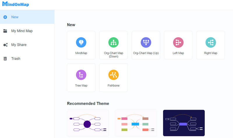
Select a layout and theme
From the next window, you will be welcomed with themes and layouts for you to get started. Alternatively, you can begin from scratch by clicking as you please.
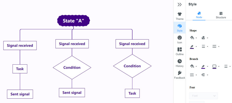
Create an SDL Diagram
After choosing a theme, add nodes by clicking the Node button on the top menu. Then, arrange the diagram to portray your system appropriately. Next, expand the Style option on the right-sidebar menu. From here, you can modify the shapes, color, and font.
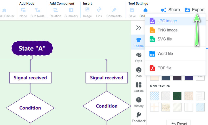
Create an SDL Diagram
To save your work, click on the Export button and choose an appropriate format. You could also share your work with others by clicking the Share icon alongside the Export button.
2. Visio
Another program that can help you create an SDL diagram in Visio. This is probably the best tool you can get when looking for a program with a comprehensive template library available. With it, you can create various diagrams, ranging from SDL, fault tree analysis, BPMN, workflow, and cross-functional flowchart diagrams. The tool is so good, especially if you are a Microsoft products user. Its interface looks similar to Word, making it easy to navigate. To help you with Visio SDL diagram creation, you may refer to the steps below.
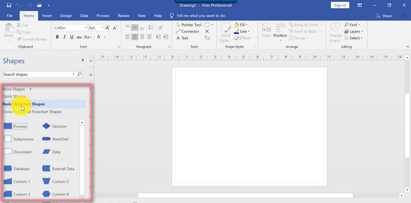
Download the Microsoft Visio on your computer and install it. Run the program afterward. Then open a blank canvas.
Now, add shapes by going to More Shapes. Hover to the Flowchart and select SDL Diagram Shapes to add them to your list of shapes options.
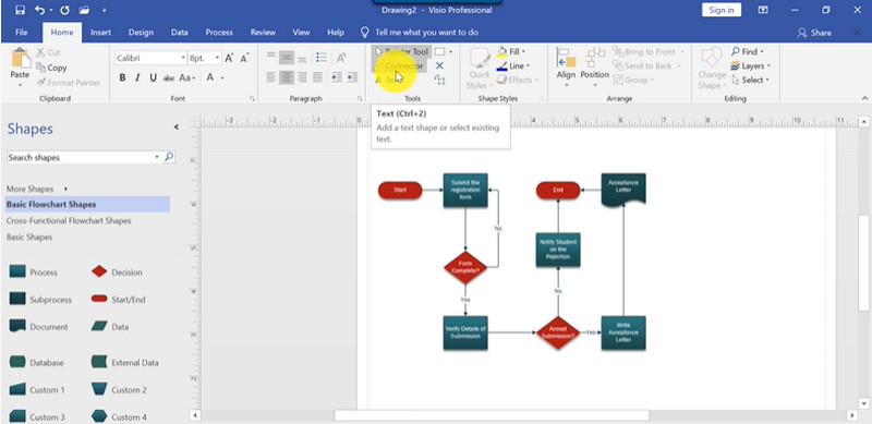
Next, add the shapes you need by dragging them into the canvas. Add text to each figure based on their functions in the system and connect them using arrows.
Fix the alignment and spacing on the drawing page. Once everything is set, save your work.
Further Reading
Part 5. FAQs on SDL Diagram
What is SDL in telecommunication?
It is the modeling language used to describe behavior, data, structure, and distributed communicating systems in real-time. It is usually in a diagram graphical specification form
What does SDL mean in an embedded system?
SDL is transformed into hardware/software implementations in embedded systems. Thus, it is useful for communication protocol design and for embedded systems.
How is SDL different from a state machine diagram?
State machine diagram is also a behavioral diagram that shows the status of an object at a specific given time. It also shows the transitions of objects in a system. Meanwhile, SDL uses elements of specification and description language to model communication machines and model object-oriented diagrams.
Conclusion
Indeed, an SDL diagram may assist you in analyzing and interpreting the system's behavior, data, and interaction in real-time systems. Through the guidelines above, you may quickly create this diagram. Meanwhile, if you find Visio expensive, you have a free alternative: MindOnMap.