Complete Understanding of UML Component Diagram with Easy Method
UML Component diagram is one of the diagram types you can find in UML diagrams. It is capable of helping users to understand the structures of a particular system. So, if you want to learn about the UML component diagrams, don’t miss the chance to read this article. You will know the various UML component diagram symbols. Moreover, you will discover the easiest method to create a UML component diagram.

- Part 1. What is A UML Component Diagram
- Part 2. Symbols of A UML Component Diagram
- Part 3. Tutorial to Create A UML Component Diagram
- Part 4. FAQs about UML Component Diagram
Part 1. What is A UML Component Diagram
UML component diagrams provide a conceptual picture of the interactions between various systems. Aspects of logical and physical modeling can both be present. Moreover, components are autonomous. It is a modular system element in UML that can be swapped out for alternatives. They contain structures of any complexity and are self-contained. Only through interfaces do the enclosed pieces communicate with other components. Furthermore, components have their interfaces, but they can also access other components' operations and services by using their interfaces. In a component diagram, the interfaces also show the connections and dependencies in a software architecture.
A Little bit Glance at A UML Component Diagram
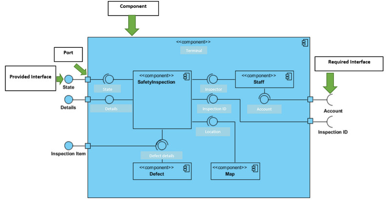
The real system under development is dissected into several high levels of functionality using a component diagram. Each part of the system has a distinct goal. It only interacts with other crucial parts when necessary. The example below is about the internal component of a larger component.
Simple Explanation:
◆ Data, including account and inspection ID, enter the component through the port on the right side. Then it's transformed into a format that the internal components can understand. The interfaces on the right are referred to as necessary interfaces. They reflect the services required for the component to perform its function.
◆ The data then travels down numerous connections to and through several other components before being output at the ports on the left. The interfaces on the left are referred to as supplied interfaces and reflect the services the presenting component will provide.
◆ A big square shape can be the system. Also, it can be a subsystem or component of the system that surrounds the internal components.
Part 2. Symbols of A UML Component Diagram
When creating a UML component diagram, you must consider the symbols. They play a big role in the diagram. In that case, you will learn all the UML component diagram symbols in this part.
Note Symbol
It gives programmers the option to attach a meta-analysis to the component diagram.

Node Symbol
It represents items that are of a higher level than components, such as hardware or software.

Component Symbol
This symbol is a thing required to carry out a stereotypical task. A component interacts with other components and offers and consumes behavior via interfaces. Consider components as a specific kind of class. A component is represented in UML 1.0 as a rectangular block with two smaller rectangles jutting out on either side. A component in UML 2.0 is represented as a rectangular block with a tiny representation of the previous component diagram shape.

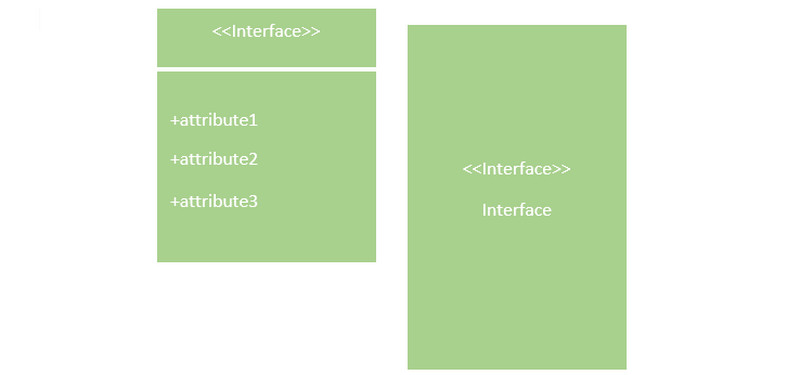
Interface Symbol
It displays any input or materials that a component either sends or gets. Textual notes or symbols, like the lollipop, socket, and ball-and-socket forms, can indicate interfaces.
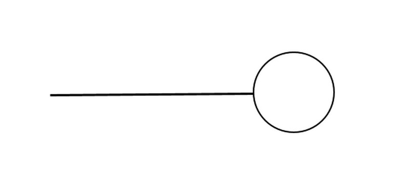
Required Interface
It receives services, functions, or data from the outside. It is also called a lollipop.
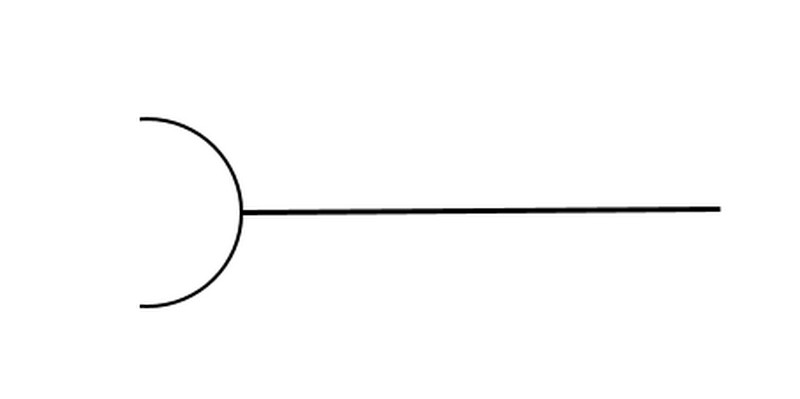
Provided Interface
It is a symbol for defining interfaces that provide functions, data, or services from the outside. The semi-circle is called a socket.
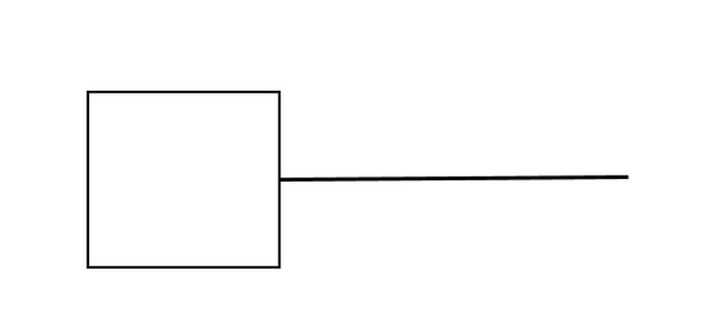
Port Symbol
The point of interaction between the component and the environment is designated separately. A tiny square serves as a symbol for ports.
Package Symbol
This symbol combines various elements in a particular system into a group. It includes component interfaces and classes.

Dependency Symbol
It demonstrates how different system components are interdependent. Dashed lines connecting one component to another represent dependencies.
Part 3. Tutorial to Create A UML Component Diagram
Do you want to create a UML component diagram but need help figuring out how to start? Worry no more. This part will give you a UML component diagram tutorial. This way, you will understand how to create a diagram. One of the ultimate tools you can use in MindOnMap. With the help of this online tool, creating a diagram would be simple. Its interface is intuitive, which is perfect for all users. Also, it has various elements you need for the diagram. It includes shapes, connecting lines and arrows, themes, font styles, colors, and more. Additionally, you can utilize this diagram maker for free, making it convenient for users. The tool is available to all web browsers, such as Chrome, Firefox, Explorer, Edge, and more.
Secure Download
Secure Download
Go to your browser and visit the official website of MindOnMap. Click the Create Your Mind Map button from the webpage.

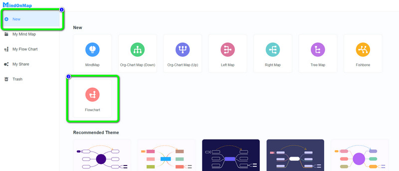
Then, another webpage will appear on the screen. On the left part of the webpage, click the New option. After that, select the Flowchart option.
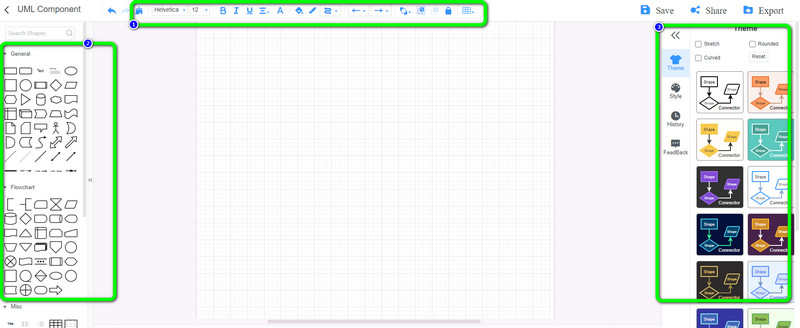
The main interface of the tool will show up on the screen. As you can see, you can use various editing tools and elements. On the upper part of the interface, these are the tools you can use for putting colors, resizing fonts, using brushes, and more. On the left interface, you can encounter various shapes that you can use for the diagram. Also, to add a fantastic theme to the diagram, navigate to the right interface and select the theme you prefer.
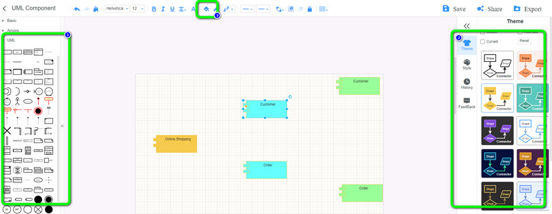
Go to the UML option to add various shapes, lines, and arrows to the canvas. Select your preferred theme to make the diagram creative and lively on the right interface. Double-left-click the shapes to add text, and go to the Fill Color option on the upper interface to put some colors on the shapes.
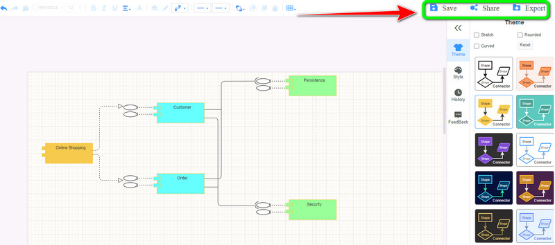
After creating the diagram, you can save it on your MindOnMap account by clicking the Save button. Click the Export button to export the diagram to various formats like DOC, PDF, SVG, JPG, PNG, and more. You can also get the link of your work by clicking the Share option and copying the link.
Part 4. FAQs about UML Component Diagram
1. What is the UML component diagram used for?
A component diagram gives a high-level system overview and details how its components are organized. Also on how they interact and depend on one another. Component diagrams offer an implementation-oriented perspective. It lets the developer see whether a system works and achieves its goals.
2. How can component diagrams help your team?
Your team can benefit from component diagrams by visualizing the physical layout of the system. Pay close attention to the parts of the system and how they interact. Place a strong emphasis on how the service behavior relates to the interface.
3. Why are component diagrams important?
Since they model and document a system's architecture, component diagrams are significant. Component diagrams serve as a system's architecture documentation. Therefore the system's developers and eventual system administrators find this work output essential to understanding the system.
4. Can I use Lucidchart to create a UML component diagram?
Absolutely, yes. Navigate to Lucidchart. Then, you can open a blank document. After that, you need to enable the shape library. Click the Shape option and check the UML, and click Save. Select the shape you want to use to start creating the diagram. Lastly, you can save your final output when you are done.
5. Is there a UML component diagram Visio template?
Yes, there is. Visio offers a component diagram template. Open Visio and navigate to the File > New option. After that, select Categories and navigate to Software and Database > UML Component. Select a blank template or choose of the three starter diagrams, and click Create. Then, use the shapes and connection points for the diagram. After creating the diagram, save the final output.
Conclusion
Well, that’s it! With the guide of this article, you have learned all things about the UML component diagram. It includes its symbols, description, and the way to create UML component diagrams. Therefore, if you want to create a UML component diagram, use the most excellent tool, which is MindOnMap. It offers everything you need when creating the diagram, making it convenient and helpful for all users.